Coating Process Guide
Silicone Masking Plugs: Powder Coating Selection Guide
Define the masking boundary, select the contact geometry and validate the complete coating cycle before approving a reusable silicone mask.
A coated thread that will not accept its mating screw can turn an otherwise acceptable metal part into a rework job. Silicone masking plugs help keep selected holes and internal features free of coating, but the result depends on the complete combination of hole geometry, plug fit, handling and process exposure.
Start with a drawing that identifies exactly where coating must stop. Then choose a plug concept, confirm its material against the actual process, and trial it on representative parts before releasing a production specification.
This guide is for coating engineers, OEM designers and purchasing teams comparing standard and custom masking solutions. It separates material screening from finished-part validation and provides a practical route from an initial sample to a controlled masking instruction.
For context on the available manufacturing formats, see the LSAN silicone product families. A masking requirement may call for a simple molded plug, a shaped cap or a more complex mask; the protected feature should decide which route deserves evaluation.
What are silicone masking plugs? Silicone masking plugs are removable elastomer components inserted into holes or recesses to protect selected surfaces during coating. A suitable design combines controlled contact geometry, a material matched to the process, and accessible removal features. Selection must be confirmed on actual parts under representative conditions.
1. Define the coating boundary before choosing a plug
“Keep the hole clean” leaves several important questions unanswered. Does the entire bore need protection, only the threaded length, the entry chamfer, or an adjacent circular contact surface? A photograph can help communicate the appearance, but a controlled drawing should identify the actual acceptance boundary.
Mark the required coated and uncoated surfaces in a section view. Distinguish an acceptable transition band from an area where any coating is unacceptable, and describe the method used to inspect that boundary after removal.
For a threaded feature, record the thread designation, tolerance class, entry geometry and usable depth. The nominal thread size alone does not describe the opening contacted by an elastomer plug, especially when chamfers, countersinks or incomplete entry threads are present.
Use a simple requirement table during the design review:
| Question | Useful input | Decision it supports |
|---|---|---|
| What must remain uncoated? | Marked drawing and section view | Plug contact surface and masking depth |
| Is the hole blind or through? | Hole depth and access from both sides | Push-in versus pull-through concept |
| Must the surrounding face be coated? | Boundary and permitted transition band | Flangeless versus flanged geometry |
| How is the mask installed? | Hand access, fixtures and gloves | Grip feature and insertion method |
| How will acceptance be checked? | Visual criteria and functional gauge | Trial and production inspection |
Consider the full process sequence as well. Establish whether plugs are installed before cleaning, after pretreatment or immediately before powder application, because that choice changes the liquids and temperatures they encounter.
Also identify who removes the plugs and at which approved process stage. Removal access can disappear when a part is loaded into a fixture, and an otherwise convenient handle can interfere with nearby masking or the coating boundary.
Engineering recommendation: approve the boundary and inspection method before discussing detailed plug dimensions. This keeps supplier samples focused on the intended function instead of encouraging a sequence of unexplained size changes.
2. Compare silicone tapered plugs, pull plugs and custom masks
The shape should follow the access and the protected surface. Essentra Components’ A Guide to High-Temperature Masking Plugs distinguishes plugs that protect internal features from caps that cover external features; they solve related but different problems.
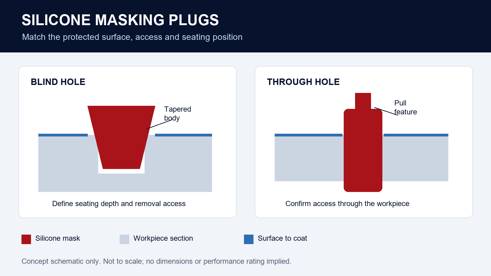
Silicone tapered plugs are a practical starting concept for holes accessed from one side. Their changing diameter provides a range of possible seating positions, but the position must still be repeatable enough to control masking depth and the coating edge.
A pull plug can be evaluated when there is usable access through the hole. A flange or shoulder may help define an edge, provided that the area it covers is actually supposed to remain uncoated.
Echo’s How To Mask Threaded Holes Before Powder Coating discusses tapered plugs for blind holes and pull plugs for through holes. Its separate threaded-hole guidance shows why protecting a chamfer can require a different feature from simply protecting the bore.
| Concept | Appropriate starting situation | What the trial must resolve |
|---|---|---|
| Tapered push plug | Blind hole or access from one side | Seating depth, retention and removability |
| Pull plug | Accessible through hole | Entry and exit masking, pull force and handle clearance |
| Flanged plug | Adjacent face also needs protection | Flange contact and final boundary |
| Flangeless plug | Coating should approach the hole edge | Edge consistency without unwanted face masking |
| Custom shaped mask | Several connected or unusual features | Installation direction, fit and manufacturability |
Treat this table as a shortlist rather than a compatibility chart. A concept that suits an accessible sample may fail to fit the assembled fixture, so evaluate the actual loading arrangement and operator access.
LSAN supports drawing-led review of custom silicone molded parts, including geometry, material, tooling and sampling requirements. For a custom masking project, that review can connect the coating boundary to a proposed molded shape; the agreed sample and process trial must establish whether the proposal works.
That is the defensible reason to involve a custom molding supplier: it can review geometry that standard catalogue shapes do not address. It does not eliminate the coating line’s responsibility to approve the finished masking result.
3. Specify the fit of powder coating plugs as a controlled window
For powder coating plugs, diameter is only part of the fit. The relevant question is whether the part seats consistently, remains where required during the process and can be removed without damaging either the mask or the coating boundary.
Avoid applying a universal oversize percentage to every hole. A tapered body, a cylindrical sealing land and a flexible flange create different contact conditions, and nominal dimensions alone do not establish their installation behavior.
Request the plug drawing, then identify which dimension controls the contact region. For a taper, specify the intended seating location or another observable installation reference rather than relying solely on the largest diameter.
The production workpiece also has a tolerance range. Include samples near the relevant limits of hole size, depth and entry geometry in the trial, instead of approving a plug against one convenient middle-of-range part.
Record these checks together:
- Whether the plug can be installed using the approved hand motion or tool.
- Whether the installed position is visible and repeatable.
- Whether the grip feature remains accessible in the production fixture.
- Whether handling before coating dislodges the plug.
- Whether the coating boundary remains acceptable after the complete cycle.
- Whether the plug can be removed intact at the approved removal stage.
For threaded holes, do not use insertion force as proof that all required threads are protected. After the trial, inspect the specified functional area and apply the agreed thread-gauging or assembly check.
Where several similar plug sizes are used on one line, create a positive identification method. A controlled bin label and a sample photograph may be more useful than relying on color alone, unless the drawing and purchasing specification formally control that color assignment.
Measure flexible samples using a defined method that does not distort the feature being inspected. When comparing supplier reports, confirm that the measurement position and conditioning are consistent; otherwise a reported difference may not describe the same characteristic.
Practical output: a successful fit review produces an approved combination of workpiece range, plug revision and installation instruction. “Fits the sample” is an observation, while that controlled combination is a basis for repeat production.
4. Match high temperature masking plugs to the full exposure
Selecting high temperature masking plugs requires more than comparing the oven display with a number in a catalogue. Ask for the rating and limitations of the actual compound and part, including the exposure duration and any restrictions on repeated use.
The Powder Coating Institute’s Frequently Asked Questions explains that powder cure depends on both metal temperature and time. Its guidance supports checking the powder-specific cure schedule and measuring the production thermal profile rather than treating oven air temperature as the complete description.
For the masking specification, record every relevant stage: preheating where used, curing, any additional bake, cooling and cleaning between uses. Have the process owner identify credible variations that a production trial should include.
| Exposure | Information to provide | Evidence to request or generate |
|---|---|---|
| Heating | Measured profile and duration | Compound guidance and representative cycle trial |
| Repeated use | Actual sequence and handling | Inspection history for the finished mask |
| Cleaning | Product identity, concentration and method | Compatibility review and trial after cleaning |
| Pretreatment | Relevant chemistry and contact conditions | Assessment of the actual formulation |
| Storage | Packaging, environment and separation | Written storage and identification instruction |
Do not transfer a sheet-material rating to a molded masking plug without confirmation. Even within the silicone family, the chosen formulation and the finished component need their own documented basis for the intended application.
Laboratory data can support screening. The public scope of ASTM D573 describes comparative evaluation of rubber under elevated-temperature aging and cautions that results do not necessarily correlate exactly with service performance.
Likewise, ASTM D471 addresses comparative effects of liquids on rubber. It is a useful reference when discussing exposure evidence with the supplier, but it does not make every silicone formulation compatible with an unspecified cleaner or treatment bath.
Ask the responsible technical teams to resolve missing information before approving the material. If the proposed plug cannot be supported for a particular cleaning stage, revise the process or material choice through that review; do not assume a successful hot-oven sample settles the chemical question.
Keep catalogue examples separate from the purchase specification. Another supplier’s temperature statement or a general industry example is not a verified LSAN product rating, and this guide intentionally assigns no universal temperature limit to silicone masking plugs.
5. Validate the complete masking cycle before release
A useful qualification trial follows the component through the same sequence it will experience in production. Looking at an unused plug confirms appearance, but the functional result is the workpiece after masking, coating and removal.
The following workflow is an engineering recommendation for organizing that trial. Set the sample quantities, acceptance limits and required repetitions according to the project’s quality requirements rather than treating this guide as a test standard.
- Freeze the trial inputs. Record workpiece revision, hole range, plug revision, material identity, coating system and process settings so that the result can be reproduced.
- Check installation. Use the intended fixture and handling method; record seating, accessibility and any adjustments needed to install the mask consistently.
- Run the production sequence. Include the relevant exposures and identify any departure from the normal route in the trial report.
- Inspect the workpiece. Evaluate the agreed coating boundary, protected depth and functional requirement after removing the mask.
- Inspect the plug. Look for damage, contamination, changed shape or handling difficulties, and record whether it is suitable for the next controlled trial cycle.
- Approve or revise. Resolve failures, repeat the affected checks after changes, and release the accepted drawing and work instruction together.
Keep observations specific. Instead of “plug failed,” record the feature affected, the process stage, the workpiece position and what changed from the intended condition.
Separate the primary result from useful secondary observations. A clean thread may satisfy one requirement, while a flange masking too much of the surrounding face fails another; neither finding should disappear inside a single general pass/fail comment.
| Observation | Questions to investigate | Approval evidence |
|---|---|---|
| Coating inside the protected area | Correct size, seating and undamaged contact region? | Accepted boundary on representative parts |
| Excess uncoated area around the hole | Flange or handle covering too much surface? | Boundary measured against drawing |
| Plug moves during handling | Installation reference and retention appropriate? | Stable position through approved sequence |
| Plug difficult to remove | Access, grip and removal stage suitable? | Repeatable removal without unacceptable damage |
| Different results after reuse | Cleaning, wear or identification changed? | Documented inspection and replacement rule |
Changing several variables at once makes investigation harder. When practical, keep the comparison controlled so the trial can distinguish a material change from a geometry change or a different installation method.
For a new custom mold, include the final production-intent material and geometry in approval. A convenient prototype can help evaluate access, but a prototype made by a different route should not silently become evidence for the finished production mask.
6. Define reuse and replacement by observable condition
“Reusable” describes a possibility, not a guaranteed number of coating cycles. Establish the replacement rule from the approved process and inspection history of the actual mask.
Assign a responsible person or station to inspect masks before they return to the production bin. Keep rejected items physically separate so a damaged plug cannot be mistaken for an unused spare during a busy shift.
The inspection instruction should describe what operators can recognize. Use reference samples or approved photographs where useful, particularly for subtle changes to a flange edge or a feature that controls seating.
Suggested conditions to review include:
- Tears, cuts or missing material at the contact surface.
- Damage to the pull handle or another removal feature.
- Permanent shape change that prevents the approved installation position.
- Residue that cannot be removed by the approved cleaning method.
- Uncertain size or material identity after mixing with other masks.
- A workpiece result outside the approved masking boundary.
These are proposed inspection categories; the production specification must define their actual acceptance limits. Rejecting a plug on appearance alone may be unnecessary in some applications, while overlooking a small defect on a critical contact edge may be unacceptable in others.
ASTM D395 evaluates compression set and is mainly applicable to static compressive service conditions. A supplier’s compression-set result can inform material discussion, but it does not establish how many insertion, heating, cleaning and removal cycles a finished mask will survive.
Keep reuse trials tied to the normal cleaning route. A replacement interval established with one cleaner or handling method needs review when that method changes.
For purchasing comparisons, collect local data on installation, removal, cleaning, rejected masks and workpiece rework. Compare cost per accepted production outcome rather than assuming the lowest unit-price plug will create the lowest total process cost.
Avoid promising a particular saving without measured results. A simple controlled trial can show whether a custom shape reduces handling or improves the boundary, but the conclusion belongs to that application and should be recorded with its conditions.
7. Build a drawing-led RFQ and an approval package
An effective enquiry gives the supplier enough context to propose a geometry and material route without inventing the missing assumptions. Include the workpiece drawing as well as the masking component concept, since the relationship between them defines the function.
If a standard plug is being replaced, provide the observed problem and the existing installation method. A sample is useful, but state whether it is unused, worn or representative of the accepted production condition.
| RFQ item | What to include |
|---|---|
| Workpiece | Drawing revision, relevant tolerances and protected surfaces |
| Mask concept | Sketch or CAD, installation direction and removal access |
| Process | Thermal profile, coating route and relevant chemical exposures |
| Material | Proposed formulation or performance requirements and documentation |
| Acceptance | Boundary, functional check, appearance and handling criteria |
| Volume | Trial quantity, normal batch and expected annual requirement |
| Controls | Identification, packaging, inspection and change-review needs |
Use the LSAN drawing-review process to organize the geometry, application and quotation inputs. Any open issue should remain visible in the quotation assumptions until the parties agree how it will be resolved.
The following examples are illustrative planning situations, not reported LSAN customer projects or performance results:
A coating engineer working on a threaded enclosure: the concern is whether the leading thread remains usable after finishing. The trial should combine the approved masking boundary with the customer’s thread check and include relevant variation in the workpiece opening.
An OEM designer with a nearby contact face: the bore and surrounding surface have different coating requirements. A flanged concept deserves review only after the drawing defines which part of that face must remain bare and the trial confirms the final boundary.
A purchasing team sourcing several similar masks: the immediate risk is mixing visually similar parts. Include revision identification, packaging separation and an approved reference in the purchase package, then verify that the proposed system works at the installation station.
For each case, decide who signs off the sample and what information that approval covers. Keep material acceptance, dimensional inspection and process validation distinguishable, even if they appear in the same report.
A later change to the hole, coating route, compound, tool or cleaning instruction should trigger a review of the affected evidence. The purpose is to preserve the accepted combination rather than assume that an old sample approval applies to every subsequent revision.
8. Questions to resolve before ordering
Can one tapered plug cover several hole sizes?
A taper can provide different seating positions, but that does not mean every position produces an acceptable masking boundary. Approve each intended workpiece range and make the installation reference clear, especially when protected depth or the entry chamfer matters.
Should a blind hole use the same mask as a through hole?
Evaluate them separately because access and protected surfaces differ. A push-in concept is often considered for one-sided access, while a pull-through concept requires usable access through the part; trial the chosen geometry in the production fixture.
Is an oven temperature setting enough to select the material?
No. Supply the relevant measured process exposure and duration, then obtain guidance for the actual compound and finished mask. The coating cure schedule and the mask’s suitability are related checks, but neither is established by the oven display alone.
How many times can silicone masking plugs be reused?
There is no universal count established by the material name. Set an inspection and replacement rule using the actual plug, coating sequence, cleaning method and accepted workpiece result, and review that rule when the process changes.
When is a custom molded mask worth evaluating?
Consider it when standard shapes cannot control the required boundary or create persistent access and handling problems. Compare a production-intent sample against the current method using defined acceptance criteria before making cost or productivity claims.
9. Send a reviewable masking requirement
The most useful specification connects four things: the protected surface, the plug’s contact geometry, the complete process exposure and the acceptance check. Once those are clear, supplier proposals and trial results become much easier to compare.
Bring the workpiece drawing, masking boundary, thermal and chemical conditions, trial quantity and expected production volume together before requesting tooling. Include the current problem if you are improving an existing mask, and distinguish confirmed requirements from items still under development.
That package gives LSAN a practical basis for discussing material, molded geometry and sample approval without assigning unsupported temperature or reuse claims. Request a silicone drawing review to start the technical assessment.